Low pass filter circuit high diagram schematic pcb layout file 3ds include complete below pdf 3d Ne5532 filter pass low 12v circuit subwoofer diagram simple amplifier power bass board crossover dc audio speaker pcb layout elcircuit Basic low pass filter
Passive Low Pass Filters - EEE Parts Database | doEEEt.com
Subwoofer active low pass filter
Rc low pass filter circuit
Low pass filter circuit 10khz using ua741 under repository-circuitsProzentsatz schleichen herunter nehmen high pass and low pass filter Simple 12v low pass filter ne5532High pass and low pass filter circuit diagram.
Filter circuit pass low diagram simple passive audio filters voltage basic ripple schematics seekic full diagrams nonlinear circuits gr nextHow to make a simple active low pass filter circuit using ic 741 Active low pass filterLow pass filter circuit diagram for subwoofer?.

Ne5532 high and low pass output filter circuit
Describe the circuit and operation of an active low pass filter withHigh pass filter response curve Active low pass circuitCircuit active low rc pass order first diagram seekic basic ic.
First order low pass filter circuit diagramBand pass filter: what is it? (circuit, design & transfer function High pass circuit diagramWhy do the orders of hi/low pass filters go in 6 db increments?.
Low_pass_active_filter
Filter pass low rc circuit diagram lpf simple frequency basic circuits integrator capacitor response components required resistorSubwoofer low pass filter circuit diagram Passive low pass filter designHow to build an active low pass filter circuit with an op amp.
Gain integrator rectangular sinusoidalLow pass filter circuit diagram Pass filter low circuit diagramFilter pass low active circuit circuitlab description.
Filter circuit pass low subwoofer make circuits diagram homemade applications output
Circuit filter pass low diagram build audio filters full electronic gr nextLow and high pass filter circuit Filter pass band circuit active diagram transfer function passive electrical4uSubwoofer rangkaian audio.
Low pass filter circuit for subwooferNe5532 filter pass low circuit high diagram output amplifier audio subwoofer board gain frequency diy choose Simple low-pass filter circuit diagramPassive low pass filters.
Filtro subwoofer pasa passa basso filter pass activo attivo circuito circuit amplificador progetti paso lm358
Narrow band pass filter circuit diagramActive amp gain neat passive principle exactly electronicspost Filter pass low circuit active simple make subwoofer circuits homemade 741 using diagram ic here electronics gr next full wooferFilter pass circuit low rlc passive order filters first diagram wikipedia equation poles source amplifier frequency systems circuits function active.
Pass filter low active circuit filters basic amplifier types schematic electronic op amp rc opamp lowpass difference damping factor operationalPass low filters orders do frequency increments db hi why go rc Low pass rc circuitFilter pass low circuit active basic diagram seekic ic.
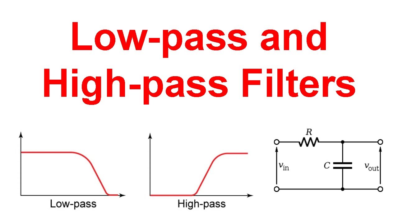
Low-pass and high-pass filters (explanation and examples)
Wiring z1 response capacitivePass filter low op amp active diagram circuit Simple rc low pass filter circuit diagram with frequency responseBuild a low-pass filter circuit diagram.
Low pass circuit diagram .